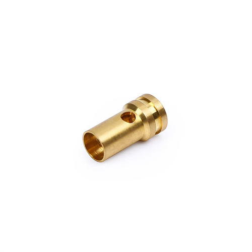
Machining of pure copper small deep hole nozzle
Pure copper small deep-hole nozzles are widely used in precision instruments, hydraulic systems, cooling devices, and other fields due to their excellent thermal conductivity, electrical conductivity, and plasticity. However, turning them, especially for small deep holes, presents many difficulties, such as easy tool wear, difficult chip removal, and difficulty ensuring hole straightness and surface roughness. Pure copper has a low hardness (Brinell hardness of approximately 35-45HB) and good plasticity, which makes it prone to tool sticking during turning, causing chips to wrap around the tool, affecting machining accuracy and surface quality. At the same time, the aperture of small deep-hole nozzles is usually small (generally less than 10mm), and the ratio of hole depth to diameter (aspect ratio) is large (usually greater than 5), resulting in insufficient tool rigidity and prone to vibration, further exacerbating the machining difficulty. Therefore, when turning pure copper small deep-hole nozzles, targeted measures must be taken in terms of tool selection, cutting parameters, and chip removal methods to ensure machining quality.
Tool selection is a critical step in turning pure copper small deep-hole nozzles, directly impacting machining efficiency and hole quality. Because pure copper exhibits high plasticity and is prone to tool sticking, tool materials should be selected from carbide with excellent wear resistance and a low coefficient of friction, such as YG-type carbide (YG6, YG8). These alloys offer excellent toughness and anti-sticking properties, effectively reducing tool sticking. For extremely small, deep holes (e.g., diameters less than 3mm), high-speed steel tools can be used. Their sharp cutting edges reduce cutting forces and vibration. Tool geometry requires careful design: a large rake angle (15°-25°) should be used to minimize cutting forces and ensure smooth chip flow; a clearance angle of 8°-12° should be used to minimize friction between the flank and the hole wall; and a lead angle of 75°-90° should be used to enhance tool rigidity and minimize vibration. Furthermore, the tool tip should be properly rounded to prevent tip chipping. A chipbreaker should be incorporated into the tool to facilitate chip breakage and discharge, preventing chip blockage.
The proper selection of cutting parameters is crucial to the turning quality of pure copper small deep-hole nozzles. This requires comprehensive consideration of the material properties of pure copper and the characteristics of deep-hole machining. The cutting speed should not be too high, as pure copper has good thermal conductivity. Excessively high cutting speeds will increase cutting temperatures, leading to accelerated tool wear and increased tool sticking. A typical cutting speed is 50-100 m/min. The feed rate should be determined based on the hole diameter and machining accuracy requirements. For small deep holes, the feed rate should be relatively low (0.05-0.15 mm/r) to reduce cutting forces and vibration and ensure hole straightness. However, the feed rate should not be too low, as this will increase machining time, reduce production efficiency, and easily cause the tool to slip within the hole. The depth of cut should be determined in layers, with each cut limited to 0.1-0.3 mm. This reduces tool load, prevents tool bending or breakage, and facilitates chip removal and heat dissipation.
Chip evacuation and cooling are key challenges in turning small, deep holes with pure copper nozzles. Due to the deep and small hole diameter, chips can easily become trapped inside, hindering machining progress and causing scratches on the hole wall, degrading surface quality, and even damaging the tool. Therefore, effective chip evacuation is essential. Commonly used methods include internal and external chip removal. Internal chip removal removes chips from the hole through internal channels within the tool and is suitable for machining relatively large, deep holes. External chip removal, on the other hand, removes chips from the gap between the tool and the hole wall and is suitable for machining small, deep holes. To improve chip removal, high-pressure cutting fluid can be used. This fluid not only cools the tool and workpiece but also flushes chips out of the hole. The cutting fluid should be an emulsion or cutting oil with good lubricity and cooling properties, and the injection pressure should be moderate (generally 3-10 MPa). Excessive pressure may cause hole wall deformation, while too low pressure will result in poor chip removal.
The machining process for pure copper small deep-hole nozzles must adhere to the principle of “roughing first, then finishing, gradually achieving the desired finish” to ensure hole dimensional accuracy and surface quality. The primary goal of the roughing stage is to remove the majority of the stock. Larger cutting depths and feed rates are acceptable, but the cutting speed must be controlled to avoid excessive heat generation. After roughing, the hole should be measured to check for straightness and diameter deviation, and appropriate corrections should be made if necessary. During the finishing stage, smaller cutting parameters should be used to reduce cutting forces and vibration, thereby improving the surface roughness. Typically, a surface roughness of Ra 1.6 to 0.8 μm is desired. Tool wear during finishing can affect machining accuracy, so regular tool wear inspections are necessary, and tools should be replaced or sharpened promptly. After completion, the nozzle should undergo a comprehensive inspection, including parameters such as hole diameter, depth, straightness, and surface roughness, to ensure compliance with the drawing specifications. Nozzles requiring sealing properties should also undergo a pressure test to check for leaks and ensure performance.