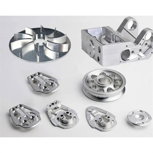
Models and basic parameters of indexable inserts
Indexable inserts, a core component of modern metalcutting tools, offer advantages such as high efficiency, long life, and excellent interchangeability. They are widely used in turning, milling, drilling, and other machining processes. The indexable insert model is a standardized identifier for its various parameters. The model number provides a quick overview of key information such as the insert’s shape, size, accuracy, chipbreaker geometry, and material, facilitating tool selection and optimizing cutting parameters. The International Organization for Standardization (ISO) and national standards (such as China’s GB and the United States’ ANSI) have clearly defined methods for compiling indexable insert models. While the details may differ slightly, the core parameters are generally expressed in the same way.
Indexable insert model numbers typically consist of multiple characters, each representing a specific parameter. For example, according to ISO standards, a typical model number consists of 10 digits, representing insert shape, clearance angle of the primary cutting edge, tolerance grade, insert construction type, cutting edge length, thickness, insert mounting method, chip breaker geometry or regrind type, and insert material. For example, in the model number “CNMG120408-PM,” “C” indicates a diamond-shaped insert (80° vertex angle), “N” indicates a clearance angle of 0°, “M” indicates a medium tolerance grade, “G” indicates a double-sided cutting edge with a hole, “12” indicates a cutting edge length of approximately 12mm, “04” indicates an insert thickness of approximately 4.76mm, “08” indicates a nose radius of 0.8mm, “P” indicates a chip breaker geometry, and “M” indicates a material code. Understanding the model number conventions helps quickly identify the basic characteristics of an insert and meet different machining requirements.
The basic parameters of indexable inserts include shape parameters, size parameters, angle parameters, and material parameters, which directly affect cutting performance. Shape parameters refer to the geometric shape of the insert. Common ones include square (S), diamond (C, D), triangle (T), and circle (R). Inserts of different shapes are suitable for different processing methods and working conditions. For example, diamond inserts (80°) are suitable for external cylindrical turning, triangular inserts are suitable for end turning, and circular inserts are suitable for profiling. Size parameters include cutting edge length, blade thickness, and tool tip radius. Cutting edge length determines the cutting depth range of the insert, blade thickness affects the rigidity of the tool, and tool tip radius affects cutting force, surface roughness, and tool life. The larger the radius, the smaller the surface roughness, but the greater the cutting force.
Angular parameters are important characteristics of indexable inserts, including the back angle, rake angle, and rake angle. The back angle is the angle between the main back face of the insert and the cutting plane. It mainly affects the friction between the back face and the workpiece. The larger the back angle, the less friction, but the lower the insert strength. Common back angles include 0°, 5°, 7°, 11°, etc. A small back angle is selected when processing hard materials, and a large back angle is selected when processing soft materials. The rake angle is usually achieved through the groove design of the insert and is divided into positive rake angle, negative rake angle, and zero rake angle. Positive rake angle inserts cut lightly and are suitable for processing plastic materials; negative rake angle inserts are strong and suitable for processing hard materials and intermittent cutting. The rake angle affects the flow direction of chips and the impact resistance of the tool. A positive rake angle causes chips to flow toward the surface to be processed, while a negative rake angle increases the strength of the tool tip.
The material parameters of indexable inserts are key factors in determining their cutting performance, primarily encompassing the base material and coating. Base materials include high-speed steel, cemented carbide, ceramics, cubic boron nitride (CBN), and diamond. Cemented carbide is the most widely used base material. Based on composition , it can be categorized into tungsten-cobalt ( WC-Co), tungsten-titanium-cobalt (WC-TiC-Co), and tungsten-titanium-tantalum-cobalt (WC-TiC-TaC-Co), suitable for machining cast iron, steel, and high-strength alloys, respectively. Coating technology can significantly improve an insert’s wear and heat resistance. Common coatings include TiN, TiCN, and TiAlN. TiN coatings offer high hardness and are suitable for low-speed cutting, while TiAlN coatings offer excellent high-temperature resistance and are well-suited for high-speed cutting. When selecting an insert material, consider the workpiece material, cutting speed, and machining method. For example, diamond-coated inserts are recommended for machining aluminum alloys, while CBN inserts are preferred for machining hardened steel.