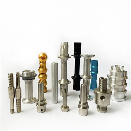
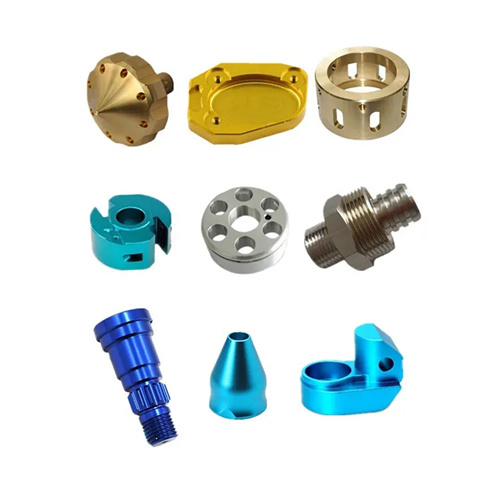
Machining special-shaped surfaces with forming turning tools
Using a forming tool to turn contoured surfaces is a highly efficient forming process. By grinding the tool’s cutting edge to a shape that perfectly matches the contour of the workpiece’s contoured surface, the desired surface can be produced in a single pass. This method is suitable for mass-produced parts with regular curved contours, such as spheres, arcs, and ellipses. Compared to manual feed or CNC interpolation machining, forming tool machining offers advantages such as high efficiency, consistent precision, and ease of operation. It is widely used in instrumentation, automotive parts, valve manufacturing, and other fields. Mastering the selection of forming tool types, geometric parameter design, sharpening methods, and turning processes is key to ensuring the quality of contoured surfaces.
According to their structure, forming turning tools can be divided into flat forming turning tools, prismatic forming turning tools and round forming turning tools. Different types are suitable for processing different special-shaped surfaces. The tool body of a flat forming turning tool is flat, and the cutting edge is ground into a special-shaped surface profile. It has a simple structure and is easy to manufacture. It is suitable for processing simple special-shaped surfaces (such as arc grooves and step surfaces) on external cylindrical surfaces or end faces, but has poor rigidity and is suitable for small-batch production. The tool body of a prismatic forming turning tool is prismatic, and the cutting edge is located on the prism surface. It has good rigidity and high precision and is suitable for processing external special-shaped surfaces, especially parts with a large length-to-diameter ratio. It can be connected to the tool holder through a dovetail groove, and is easy to install and adjust. The tool body of a round forming turning tool is cylindrical, and the cutting edge is ground on the cylindrical surface. It can process internal and external special-shaped surfaces, has strong versatility, and after grinding, the tool position can be adjusted to compensate for dimensional changes. It has a long service life and is suitable for mass production. When selecting the type of forming turning tool, the complexity of the special-shaped surface, production batch and precision requirements need to be considered. Flat tools are used for simple special-shaped surfaces, prismatic tools are preferred for external special-shaped surfaces, and round tools are used for internal and external special-shaped surfaces or large-scale production.
The geometric parameters of a forming turning tool must balance cutting performance and contour accuracy. These parameters primarily include the rake angle, clearance angle, rake angle, and cutting edge profile. The rake and clearance angles are adjusted based on the workpiece material and tool type. When machining steel, the rake angle is 10°-15°, while for cast iron, it’s 5°-10°. The clearance angle is typically 6°-10°. For prismatic and round forming turning tools, the clearance angle is determined by the tool’s tilt angle during installation, while for flat forming turning tools, the clearance angle is ground directly. A rake angle of 0°-5° ensures chips are ejected outward from the workpiece, avoiding scratches on the machined surface. The cutting edge profile is the core of the forming turning tool and must perfectly align with the contour of the workpiece’s feature surface. However, consideration must be given to errors during tool installation and cutting. For example, when machining spherical surfaces, the arc radius of the tool’s cutting edge should be 0.01-0.03mm smaller than the workpiece’s spherical radius to compensate for radial offset during tool installation. When machining conical surfaces, the cutting edge angle should be 30′-1° greater than the workpiece’s taper angle to offset elastic tool deformation caused by cutting forces. The contour accuracy needs to be tested by a template or projector, with an error of ≤0.02mm.
Grinding of profile turning tools requires ensuring an accurate cutting edge profile and a smooth surface. Grinding methods vary depending on the tool type. Flat profile turning tools can be sharpened on a tool grinder using a profile grinding wheel. The grinding wheel shape should be aligned with the tool profile. During grinding, the wheel axis should be parallel to the tool rake face. Surface roughness Ra should be ≤ 0.8μm. Grinding of prismatic profile turning tools focuses on maintaining the cutting edge profile and clearance angle. A dedicated fixture is used to position the tool, and a bowl-shaped grinding wheel is used to grind the tool rake face, ensuring uniform clearance angles at all points. Grinding of circular profile turning tools requires ensuring both profile accuracy and cylindricity. This is performed on a circular tool grinder. Using the tool center hole as a reference, the relative position of the grinding wheel and tool is adjusted to ensure the cutting edge profile meets the requirements after grinding. After sharpening, the cutting edge profile should be checked using a profile template, with a deviation of ≤ 0.01mm. The rake and clearance angles should be checked using an angle ruler, with an error of ≤ ±30°. The cutting edge should be polished with an oilstone to remove burrs and micro-nicks to improve tool durability.
The clamping and adjustment of special-shaped surfaces with forming turning tools have a significant impact on machining accuracy, and the relative position of the tool and the workpiece must be accurate. The workpiece clamping must be firm and reliable. For shaft parts, a double-thimble or three-jaw chuck and tailstock combination clamping is used, with radial runout ≤0.02mm; disc parts are clamped with a three-jaw or four-jaw chuck, with end face runout ≤0.01mm. The installation of the forming turning tool must be precisely centered, and the symmetrical center line of the cutting edge must coincide with the axis of the workpiece, with a deviation ≤0.01mm. Adjustment can be made through trial cutting: turn a shallow mark on the end face of the workpiece and measure whether the mark width is symmetrical. If it is not symmetrical, adjust the lateral position of the tool. The tool height must be the same height as the workpiece axis, with a deviation ≤0.02mm. A height gauge or template can be used for calibration. Improper height will lead to deviation in the size of the special-shaped surface. For example, when machining a sphere, a tool that is too high will reduce the radius of the sphere. For prismatic and circular forming turning tools, they need to be installed at an inclined angle at a specified angle to obtain the required clearance angle. The inclination angle is equal to the tool clearance angle, and the deviation is ≤30′. This can be achieved using angle shims or special tool holders.

The process parameters and quality control for turning feature surfaces with forming turning tools require targeted settings. The cutting speed is selected based on the tool and workpiece material. High-speed steel forming turning tools should use 10-30 m/min, while carbide forming turning tools should use 50-100 m/min. This speed can be increased by 20%-30% when machining non-ferrous metals. The feed rate should be 0.1-0.3 mm/r, with a higher value for rough turning to improve efficiency and a lower value for finish turning to ensure surface quality. The depth of cut should be equal to the maximum machining allowance of the feature surface, and the workpiece should be machined in a single pass. For workpieces with larger allowances, two passes can be used: the first rough turning to remove most of the allowance, followed by a second finish turning with a forming turning tool. Adequate cooling and lubrication are essential, using extreme pressure emulsion for steel and kerosene for cast iron to prevent chip adhesion and tool wear. Quality inspection is performed using a template comparison method or a three-dimensional coordinate measuring machine. The clearance between the template and the workpiece feature surface should be ≤0.03 mm. Surface roughness Ra should be ≤3.2 μm, with critical surfaces requiring Ra ≤1.6 μm. Common Defects and Solutions: If contour errors exceed tolerance, resharpen the tool or adjust its mounting position. Surface scratches require chip cleaning and enhanced cooling. Dimensional deviations can be corrected by adjusting the tool’s radial position. By properly selecting tools, precisely adjusting the clamping setup, and optimizing cutting parameters, using forming turning tools to turn special-shaped surfaces can achieve efficient, high-precision machining to meet the demands of mass production.