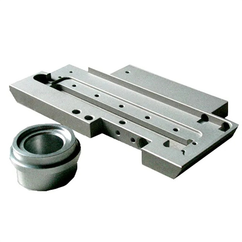
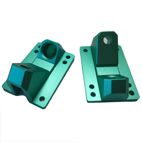
Machining of cast iron bevel gear seat
Cast iron bevel gear seats are supporting components of bevel gear transmission systems, used to secure the bevel gear shaft and maintain its installation angle. They are typically made of gray cast iron (HT250, HT300) or ductile iron (QT500-7). After aging, they achieve a hardness of 180-230 HBW, providing sufficient rigidity and wear resistance. Their structure features a bevel gear shaft hole (at an angle to the axis), a mounting flange, a locating stop, and bolt holes. The angular accuracy of the shaft hole (perpendicularity or inclination to the flange surface) must be ≤±10°, and the coaxiality between the shaft hole and the stop must be ≤0.02mm. Machining operations require addressing issues such as angular positioning, insufficient rigidity, and dimensional accuracy. High-precision machining is achieved through specialized fixtures and precision adjustment.
The machining process for cast iron bevel gear seats must be designed based on the specific shaft hole angles. A typical process is: blank casting → aging treatment (250°C x 5h) → rough turning of the flange, spigot, and outer contour → marking to determine the shaft hole position and angle → rough boring of the shaft hole → semi-finish turning of the flange and spigot → semi-finish boring of the shaft hole (according to the required angle) → finish turning of the flange and spigot → finish boring of the shaft hole → drilling of bolt holes → final inspection. After casting, the blank requires aging treatment to eliminate casting stress and prevent post-machining deformation. During rough machining, most stock is removed, leaving a 1-2mm allowance on the flange, 1-1.5mm on the spigot , and 2-3mm on the shaft hole. Marking must accurately mark the shaft hole angle and position, with an angular deviation of ≤±5°, to provide a reference for subsequent boring. Semi-finishing and finishing operations must follow the “face first, hole last” principle, using the flange and spigot as a reference for machining the shaft hole to ensure positional accuracy.
Machining the flange surface and the flange is essential for ensuring positioning accuracy. For rough turning of the flange surface, a carbide facing tool (YG8) is used at a cutting speed of 60-80 m/min, a feed rate of 0.2-0.3 mm/r, a cutting depth of 2-3 mm, and a flatness control of ≤0.1 mm. For rough turning of the flange surface, a 90° external cylindrical turning tool is used at a cutting speed of 50-70 m/min, a feed rate of 0.15-0.25 mm/r, and a cutting depth of 1-2 mm. The flange diameter should be 1-2 mm larger than the design dimension, and the perpendicularity to the flange surface should be ≤0.05 mm. For semi-finish turning of the flange surface, a YG6 tool is used at a cutting speed of 80-100 m/min, a feed rate of 0.15-0.2 mm/r, a cutting depth of 0.5-1 mm, and a flatness of ≤0.05 mm, with a surface roughness Ra of ≤3.2 μm. The precision turning of the flange surface and the stopper must be completed in the same process, using high-speed steel tools (W18Cr4V), cutting speed 40-60m/min, feed rate 0.05-0.1mm/r, cutting depth 0.1-0.3mm, stopper size accuracy IT7 level, perpendicularity to the flange surface ≤0.01mm, surface roughness Ra ≤1.6μm.
Angling the shaft hole is a challenge in turning cast iron bevel gear housings, requiring the use of an angle fixture or the angle programming function of a CNC lathe. For bevel gear housings with a 90° angle between the shaft hole and the flange surface, this can be achieved on a standard lathe by adjusting the tailstock offset or using an angle shim. For other angles (such as 45° and 60°), a dedicated angle fixture is required with an angular accuracy of ≤±5°. The workpiece is positioned between the stop and the flange surface, and the clamping force is controlled at 3-5kN to prevent deformation. A YG8 carbide boring tool is used for rough boring of the shaft hole, with a cutting speed of 50-70m/min, a feed rate of 0.2-0.3mm/r, a cutting depth of 1-2mm, and a shaft hole diameter 1-2mm larger than the design size. Angular deviation is ≤±30°. Semi-finish boring uses a YG6X tool with a cutting speed of 70-90 m/min, a feed rate of 0.1-0.15 mm/r, a cutting depth of 0.5-1 mm, an angular deviation of ±15°, and a surface roughness of Ra ≤ 3.2 μm. Finish boring of shaft holes uses a high-speed steel boring tool with a cutting speed of 30-50 m/min, a feed rate of 0.05-0.1 mm/r, a cutting depth of 0.1-0.3 mm, and kerosene cooling. The shaft hole dimensional accuracy is IT7, with an angular accuracy of ≤ ±10° and a surface roughness of Ra ≤ 1.6 μm.
Bolt and locating holes must be machined with guaranteed positional accuracy, with a positional deviation of ≤±0.1mm. Drilling is performed using a jig with a drill bit diameter selected according to the thread pitch (e.g., 8.5mm for an M10 bolt hole). After drilling, the hole mouth is countersunk (to a depth of 2-3mm) to facilitate proper alignment of the bolt head. Tapping is performed using a 6H-grade machine tap and a 3:1 ratio of kerosene and engine oil as the cutting fluid to ensure a smooth thread surface. The locating holes are drilled to H7-grade precision using a drill-reamer-reamer process. A carbide reamer is used for reaming, with a cutting speed of 5-10m/min and a feed rate of 0.5-1mm/r. The positional deviation relative to the axial hole is ≤±0.05mm. During quality inspection, use an angle ruler or a three-dimensional coordinate measuring machine to check the shaft hole angle, a dial indicator to measure the coaxiality of the shaft hole and the spigot, and a feeler gauge to check the dimensions of the bolt holes and locating holes. This ensures that the meshing clearance (0.1-0.2mm) and contact spot (≥60% in both tooth height and tooth width) of the bevel gears meet the requirements during assembly. Through rational process design and precision machining, the cast iron bevel gear housing ensures the smoothness and service life of the bevel gear transmission, with an operating noise level of ≤85dB.