Machining of cast iron shaft bracket
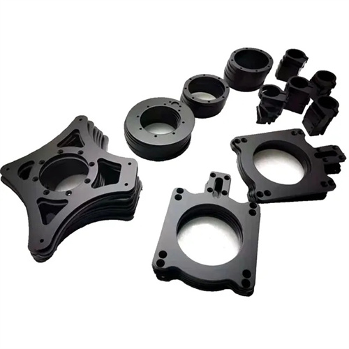
A cast iron symmetrical shaft bracket is a supporting component consisting of two symmetrical halves connected by bolts. It is widely used to secure rotating components such as machine tool spindles and drive shafts. Made primarily of gray cast iron (HT250, HT300), it offers excellent rigidity and shock absorption. This component’s structural features include a mating surface, a shaft hole, bolt holes, and a locating pin hole. The flatness of the mating surface must be ≤0.03mm/100mm, and the perpendicularity between the shaft hole and the mating surface must be ≤0.02mm/100mm. Machining must ensure the accuracy of the plane, inner hole, and step, while ensuring interchangeability between the two halves. Machining cast iron symmetrical shaft brackets requires addressing issues such as mating surface deformation, shaft hole coaxiality, and positioning accuracy. High-precision assembly is achieved through a well-planned machining sequence and clamping method.
The machining process for cast iron scissor shaft brackets follows the principle of “first overall, then scissoring,” and “first benchmark, then detailing.” The typical process is: blank casting → aging treatment (to eliminate internal stresses) → rough turning of the outer contour and mating surfaces → scribing → drilling of bolt and dowel holes → scissoring → semi-finish turning of the mating surfaces → finish turning of the axle holes and steps after assembly → final inspection. After casting, the blanks undergo natural aging (storage for 3-6 months) or artificial aging (250-300°C for 4-6 hours) to reduce internal stress and prevent post-machining deformation. During the rough turning phase, most stock is removed, leaving a 0.5-1mm finishing allowance on the mating surfaces and a 1-2mm allowance on the shaft hole. Scissoring is performed using wire EDM or sawing, with a flatness of ≤0.05mm to ensure symmetry between the two halves. During assembly, scissoring is performed using dowel pins and bolts, with a tightening torque of 20-30N · m to ensure overall rigidity after assembly.
Machining the mating surfaces is critical to ensuring assembly accuracy. Rough turning of the mating surfaces uses a carbide facing tool (YG8) at a cutting speed of 60-80 m/min, a feed rate of 0.2-0.3 mm/r, and a cutting depth of 2-3 mm. After turning, check flatness with a flatbed and feeler gauge to maintain an accuracy of ≤0.1 mm. Semi-finish turning of the mating surfaces uses a YG6 tool at a cutting speed of 80-100 m/min, a feed rate of 0.15-0.2 mm/r, and a cutting depth of 0.5-1 mm. Surface roughness is controlled to Ra ≤3.2 μm. Finish turning of the mating surfaces should be performed in the assembled state using a wide-blade tool (blade width 30-50 mm) at low speeds, a cutting speed of 30-50 m/min, a feed rate of 0.05-0.1 mm/r, and a cutting depth of 0.1-0.3 mm. Ensure flatness ≤0.03 mm and parallelism ≤0.02 mm on both mating surfaces. After machining the mating surfaces, burrs must be removed and the surfaces must be lightly rubbed with sandpaper (grit size 120#) to avoid gaps during assembly.
The turning of the shaft hole and step must be performed in the assembled state to ensure the coaxiality of the two shaft holes (≤0.02mm). For rough boring of the shaft hole, a YG8 carbide boring tool is used, with a cutting speed of 50-70m/min, a feed rate of 0.2-0.3mm/r, a cutting depth of 1-2mm, and the shaft hole diameter is 1-2mm larger than the design size. For semi-finishing boring, a YG6 tool is used, with a cutting speed of 70-90m/min, a feed rate of 0.15-0.2mm/r, a cutting depth of 0.5-1mm, and a finishing allowance of 0.3-0.5mm for the shaft hole. Fine boring of shaft holes uses a high-speed steel boring tool (W18Cr4V) at a cutting speed of 30-50 m/min, a feed rate of 0.05-0.1 mm/r, and a cutting depth of 0.1-0.3 mm. Kerosene cooling is used. Surface roughness Ra ≤ 1.6 μm, with dimensional accuracy reaching IT7 (e.g., φ80H7, upper deviation + 0.03 mm, lower deviation 0). The perpendicularity between the step surface and the shaft hole must be ≤ 0.01 mm/100 mm. A 90° boring tool is used, boring the hole first, then turning the step surface, ensuring a flatness of ≤ 0.02 mm.
Positional accuracy must be ensured during the machining of dowel pin and bolt holes. Dowel pin holes must meet H7 precision, with a distance deviation of ≤±0.02mm from the mating surface. A drilling, reaming, and reaming process is used: the drilled hole diameter is 0.5mm smaller than the pin hole diameter, and the hole is reamed to 0.1-0.2mm smaller than the pin hole diameter. A carbide reamer is used for reaming, with a cutting speed of 5-10m/min and a feed rate of 0.5-1mm/r. After reaming, a plug gauge is used to ensure smooth pin insertion and a clearance of ≤0.01mm. Bolt holes are drilled and tapped, achieving a thread accuracy of 6H. The pre-tapping diameter is calculated using the formula D = d – 1.0825p (where d is the major thread diameter and p is the pitch). For example, the drill diameter for an M12 bolt hole is 10.2mm. A cooling lubricant (kerosene + engine oil = 3:1) is used during tapping to prevent surface roughness. During quality inspection, after assembling the two halves, a dial indicator is used to measure the coaxiality of the shaft holes and the perpendicularity of the stepped surfaces. A flat plate is used to check the fit of the mating surfaces (without inserting a feeler gauge) to ensure that there is no looseness or runout after assembly. By strictly controlling the accuracy of each link, the cast iron mating shaft bracket meets the support requirements of rotating components, with a vibration of ≤ 0.05mm/s during operation.