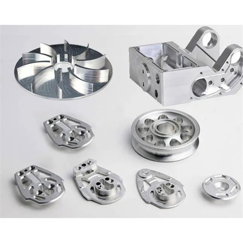
Machining of cast iron thin-walled step sleeve
Cast iron thin-walled stepped sleeves are cast iron sleeves with multiple steps and a wall thickness to inner diameter ratio of less than 1:20. They are commonly used in machine tool guide rails, pump bodies, valves, and other equipment for guiding, sealing, or supporting functions. Mostly made of gray cast iron (HT200, HT300) or ductile iron (QT400-15), they offer excellent wear resistance and shock absorption. However, their thin-walled structure results in poor rigidity, making deformation and vibration during turning difficult, making it difficult to ensure machining accuracy. Machining cast iron thin-walled stepped sleeves requires addressing issues such as clamping deformation, cutting vibration, and dimensional accuracy control. High-precision machining can be achieved by optimizing clamping methods, tool parameters, and cutting processes.
The structural characteristics of thin-walled cast iron stepped sleeves present significant machining challenges. These challenges include: The thin wall thickness (typically 3-10mm) easily leads to elastic deformation under clamping force, resulting in dimensional deviations when the clamp is released after machining. For example, a sleeve with an inner diameter of 100mm and a wall thickness of 5mm can experience clamping deformation of up to 0.1-0.2mm. The numerous steps lead to uneven structural rigidity, which can easily cause vibration during turning and produce chatter marks on the surface (roughness Ra ≥ 6.3μm). Cast iron is brittle, easily generating chip breakage during cutting, which can scratch the machined surface. High coaxiality between the inner and outer diameters (≤0.03mm) is required, but the thin-walled structure makes it difficult to ensure positioning accuracy. These challenges necessitate low-stress clamping, low-vibration cutting, and high-precision measurement during machining to meet design requirements (typically dimensional tolerances of IT8-IT9, with geometric and positional tolerances ≤0.05mm).
Cast iron thin-walled stepped sleeves should be clamped using “flexible clamping” technology to avoid deformation caused by rigid clamping. For roughing, a three-jaw chuck with soft jaws should be used. The soft jaws should be pre-machined to the workpiece’s outer diameter, with a contact area of ≥80%. The clamping force should be controlled at 2-3 kN, reducing the pressure per unit area by increasing the contact area. For semi-finishing and finishing, a mandrel or expansion sleeve should be used for positioning. The fit between the mandrel and the inner bore should be H7/g6, with a clearance of 0.01-0.02 mm. The mandrel should be made of 45 steel (quenched and tempered) with a surface roughness of Ra ≤ 0.8 μm. This ensures positioning accuracy while minimizing workpiece compression. For extra-long thin-walled sleeves (length > 500 mm), additional steady rest support is required. The steady rest support block should be made of wear-resistant cast iron, with a contact pressure of ≤ 0.1 MPa. The support block should be lubricated to reduce vibration caused by friction. When clamping, a copper sheet should be placed between the workpiece and the fixture to avoid damaging the surface. The copper sheet is 0.1-0.2mm thick, has good ductility, and can evenly transmit the clamping force.
Machining tools should be selected to suit the cutting characteristics of cast iron and the machining requirements of thin-walled parts. External turning tools should be made of YG carbide (YG6, YG8). YG tools offer toughness and wear resistance suitable for machining cast iron and are less susceptible to built-up edge. Tool angles: A rake angle of 0°-5° reduces cutting forces; a relief angle of 6°-8° ensures a sharp cutting edge; a lead angle of 75°-90° reduces radial cutting forces and workpiece deformation; and a rake angle of -3°-0° allows chips to be ejected outward, avoiding surface scratches. Internal boring tools should use solid carbide shanks with a diameter as large as possible (0.6-0.7 times the hole diameter) to minimize shank vibration. A shank length-to-diameter ratio of ≤3 is recommended for maximum rigidity. During sharpening, the tool edge should be sharp, with a surface roughness Ra ≤ 0.4μm to avoid chipping during cutting. The cutting fluid should be kerosene or a mixture of kerosene and engine oil (ratio 3:1), which helps to remove chips while cooling and reducing scratches on the surface.
Optimizing cutting parameters is crucial for controlling vibration and deformation. During rough turning, the goal is to quickly remove stock. A cutting speed of 60-80 m/min, a feed of 0.15-0.2 mm/r, and a depth of cut of 1-2 mm are used. Upward milling is employed to reduce friction between the tool and the workpiece. During semi-finish turning , the cutting speed is increased to 80-100 m/min, the feed reduced to 0.1-0.15 mm/r, and the depth of cut is 0.5-1 mm, leaving a 0.3-0.5 mm stock allowance for finishing. For finish turning, a low-speed turning method is employed with a cutting speed of 50-60 m/min, a feed of 0.05-0.1 mm/r, and a depth of cut of 0.1-0.3 mm. Down milling achieves excellent surface quality, with a surface roughness Ra ≤ 1.6 μm. Continuous cutting is essential during the cutting process, avoiding stops midway to prevent tool marks on the workpiece surface. For multi-step structures, the larger diameter step should be machined first, followed by the smaller diameter step, to gradually reduce the impact of cutting forces on the workpiece.
Quality inspection and deformation control are the final steps in the production of thin-walled cast iron step sleeves. Dimensional accuracy testing should be performed 10-15 minutes after the workpiece is released from the fixture. Once elastic deformation has fully released, the inner diameter is measured with an internal micrometer and the outer diameter is measured with an external micrometer. Deviations are controlled within the IT8 tolerance range (e.g., for a φ100H8 inner diameter, the upper deviation is +0.054mm and the lower deviation is 0). Geometric tolerance testing: The coaxiality of the inner and outer diameters is measured with a micrometer and a pressure gauge to ≤0.03mm. The flatness of the step surface is measured with a flat plate and feeler gauge to ≤0.02mm/100mm. Surface quality is tested with a roughness tester, with Ra ≤1.6μm for the outer diameter and ≤3.2μm for the inner diameter. Casting defects such as pores and shrinkage are prohibited. Common defects and solutions: Oval inner holes are often caused by uneven clamping force, requiring readjustment of the soft jaws or mandrel; surface chatter marks require reducing cutting speeds or replacing a more rigid toolholder; dimensional deviations require trial cutting, measuring after each cut to gradually approximate the design dimensions. Through appropriate clamping, tooling, and parameter selection, the machining accuracy of cast iron thin-walled step sleeves can consistently meet design requirements, with a clearance after assembly controlled within 0.01-0.03mm, ensuring the normal operation of the equipment.