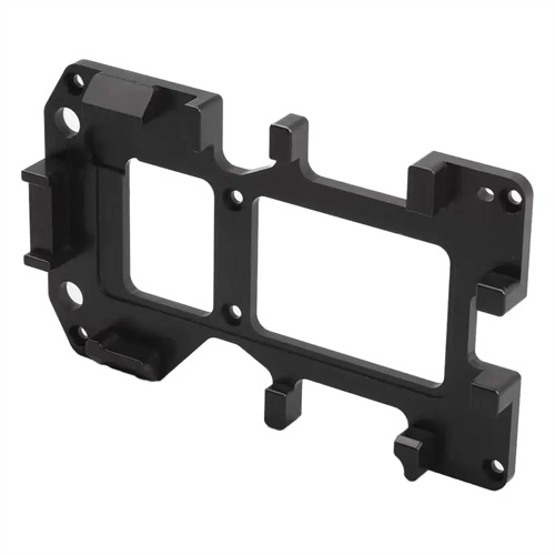
Machining of T-shaped bushings
As a critical component in mechanical transmission systems, the quality of T-shaped bushings directly impacts the equipment’s assembly precision and operational stability. When turning T-shaped bushings, it’s crucial to first understand the part’s structural characteristics: it typically consists of two parts, a horizontal axis and a vertical axis, forming a “T” shape at their intersection, and often faces stringent requirements for coaxiality and perpendicularity. Therefore, pre-machining process planning is crucial. Appropriate tools and cutting parameters must be selected based on the part’s material (such as 45 steel, cast iron, or stainless steel), along with a sound clamping strategy.
Choosing the clamping method is the primary step in turning T-sleeves. Direct clamping with a three-jaw chuck can cause workpiece deformation due to uneven clamping force, especially when the sleeve wall is thin. In this case, consider using a specialized fixture or mandrel for clamping, utilizing end-face positioning and axial clamping to reduce the impact of radial forces on the workpiece. For example, for a stepped T-sleeve, first secure one end of the horizontal shaft with the mandrel to ensure its axis of rotation aligns with the spindle axis. Then, support the other end with the tailstock center to enhance workpiece rigidity and lay the foundation for subsequent external cylindrical and end-face turning.
Tool selection should be considered based on the machining location and material characteristics of the T-shaped sleeve. When turning the external diameter and end face, high-speed steel tools are suitable for low-speed cutting of brittle materials, while carbide tools are more suitable for high-speed cutting of steel or stainless steel, effectively improving machining efficiency and surface quality. For right-angle steps at T-shaped intersections, a 90-degree external turning tool should be used, and attention should be paid to the tool’s primary and secondary rake angles to avoid overcutting or residual burrs at the root of the step. Furthermore, the quality of the tool’s sharpening should not be neglected. A sharp blade reduces cutting forces, reduces the risk of workpiece deformation, and extends the tool’s life.
Properly setting cutting parameters directly impacts the machining accuracy and production efficiency of T-shaped bushings. Regarding cutting speed, when machining 45 steel, carbide tool speeds can be controlled within 80-120 m/min. When machining difficult-to-cut materials like stainless steel, the speed should be reduced to 50-80 m/min to minimize tool wear. The feed rate is typically determined by surface roughness requirements. For roughing, 0.2-0.3 mm/min is recommended, while for finishing, it should be reduced to 0.1-0.15 mm/min. The back-cut depth should be selected based on the principle of “removing excess during roughing and ensuring accuracy during finishing.” For roughing, a 2-3 mm stock removal can be achieved, while for finish turning, the stock should be controlled at 0.5-1 mm to ensure that the part’s dimensional tolerances meet design requirements.
Quality inspection and error control during the machining process are crucial to ensuring the quality of T-sleeves. After each process, dimensions such as the outer diameter and step length are measured using tools such as vernier calipers and micrometers, and the roundness and coaxiality of the workpiece are checked using a dial indicator. If any deviations are detected, the cause should be promptly analyzed and process parameters adjusted. For example, dimensional deviations due to tool wear require resharpening or tool replacement, while runout due to loose clamping requires re-tightening of the workpiece. For T-sleeves with higher precision requirements, an aging treatment can be performed after machining to eliminate internal stresses and prevent deformation caused by stress release during subsequent use, thereby ensuring the long-term stability of the part.