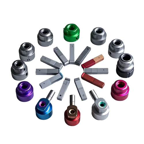
Common roller outer circle shapes and applications of roller rolling tools
Roller-type rolling tools apply pressure to the workpiece surface, causing plastic deformation of the workpiece’s surface metal, thereby improving surface quality and dimensional accuracy. They are widely used in industries such as machinery manufacturing, automotive, and hydraulics. The outer diameter of the roller is a key factor influencing the rolling effect. Different outer diameters are suitable for different workpiece shapes and processing requirements. Choosing the right roller outer diameter can significantly improve rolling efficiency and processing quality.
Cylindrical rollers are one of the most commonly used roller outer diameters. Their outer diameter is a standard cylindrical surface with a straight generatrix. Cylindrical rollers are suitable for rolling the outer surfaces of cylindrical workpieces, such as shafts, piston rods, and optical shafts. During the rolling process, the cylindrical roller’s contact line with the workpiece forms a straight line, which evenly applies pressure to the workpiece surface, causing uniform plastic deformation of the surface metal. This reduces surface roughness (to Ra 0.02-0.8μm) and increases surface hardness (typically by 20%-50%). Cylindrical rollers have a simple structure, are easy to manufacture, and offer low cost, making them suitable for conventional rolling processes in mass production. When using a cylindrical roller, the appropriate size should be selected based on the workpiece diameter. The roller diameter is generally 1.5-3 times the workpiece diameter to ensure stability during the rolling process.
The outer diameter of a conical roller is conical, with its generatrix forming a certain angle with the axis (usually 5° to 30°). This makes it suitable for rolling conical workpiece surfaces or workpieces with tapers, such as tapered shafts, tapered holes, and valve spools. During the rolling process, the contact line is parallel to the workpiece’s cone generatrix, adapting to changes in the workpiece’s taper and ensuring uniform rolling across the entire conical surface. Compared to cylindrical rollers, the design of a conical roller requires precise control of the cone angle to match the workpiece’s taper. The angle error should be no greater than 0.5°, otherwise the rolling force will be unevenly distributed, affecting the processing quality. Conical rollers are often used in the processing of conical sealing areas on hydraulic components, effectively improving the sealing and wear resistance of the conical surface.
Spherical rollers have a spherical outer surface, with a radius of curvature determined by the workpiece’s curvature requirements. They are suitable for rolling spherical workpieces or surfaces with arc transitions, such as ball studs, the arc surface of bearing outer rings, and the fillet of molds. The contact between the spherical roller and the workpiece is point contact, adapting to changes in the curved surface. The roller’s movement ensures uniform rolling of the curved surface, avoiding localized stress concentration. The roller’s radius of curvature should be slightly larger than that of the workpiece (generally 5% to 10% larger) to ensure good contact during rolling and reduce roller wear. Spherical rollers require high manufacturing precision, with the roundness error of the spherical surface no greater than 0.005mm and a surface roughness of Ra0.02μm or less to ensure smoothness after rolling.
The outer circumference of a grooved roller is grooved. The cross-sectional shape of the groove can be designed based on the groove shape of the workpiece, such as a V-groove, U-groove, or rectangular groove. It is suitable for rolling grooved surfaces on workpieces, such as keyways, grooves, and the root circle of gear teeth. The groove dimensions of the grooved roller must precisely match those of the workpiece groove. The width, depth, and angle errors of the groove should be controlled within a range of 0.01 to 0.03 mm to ensure the dimensional accuracy of the groove after rolling. During the rolling process, the cutting edges on both sides of the grooved roller need to be passivated to avoid scratching the workpiece surface. At the same time, the bottom of the groove should adopt an arc transition to reduce stress concentration. Grooved rollers are often used for groove processing on shaft parts, which can significantly improve the wear resistance and fatigue strength of the groove surface.
Combination rollers combine multiple external cylindrical shapes, such as cylindrical-conical or cylindrical-spherical combinations. These rollers are suitable for rolling complex workpiece surfaces, such as stepped shafts and cylindrical surfaces with arc transitions. Combination rollers can roll multiple surfaces of varying shapes simultaneously, reducing tool changes and improving processing efficiency. The design of combination rollers must ensure smooth transitions between the various shapes to avoid sudden stress changes during the rolling process, which could affect the workpiece surface quality. For example, a cylindrical-spherical combination roller can be used to roll shafts with spherical ends. The cylindrical portion rolls the shaft’s outer diameter, while the spherical portion rolls the spherical surface of the shaft end, completing both surfaces in a single rolling operation. Combination rollers are challenging to manufacture and require precision grinding to ensure the positional accuracy and surface quality of each component.