Involute gear hobs
An involute gear hob is a tool used to produce involute gear tooth profiles. It operates based on the principle of generating, meshing the hob with the gear being machined to create the desired involute tooth profile on the gear blank. Involute gears are widely used in mechanical transmission systems due to their smooth transmission and high load-bearing capacity. As one of the most commonly used tools for machining involute gears, the design and manufacturing quality of the hob directly impacts the machining accuracy and performance of the gear. The involute gear hob’s appearance resembles a helical gear, with an axial cross-section that resembles a rack tooth profile. During machining, the hob’s rotational motion combines with the workpiece’s rotational motion to form a generating motion. Simultaneously, the hob performs an axial feed motion along the workpiece, producing a continuous tooth profile. Basic hob parameters include module, pressure angle, number of starts, and helix angle. These parameters must match those of the gear being machined to ensure proper meshing.
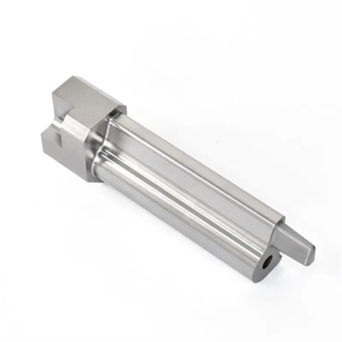
The structure of an involute gear hob is complex, primarily consisting of a cutter body, teeth, chip flutes, and support blocks. The cutter body is typically constructed of high-speed steel or carbide. High-speed steel hobs offer excellent toughness and machining performance, making them suitable for low- and medium-speed machining. Carbide hobs, on the other hand, offer greater wear and heat resistance, making them suitable for high-speed cutting and machining high-strength materials. The teeth are the cutting element of the hob. Each tooth has a rake face, a flank face, and a cutting edge. The intersection of the rake and flank faces forms the primary cutting edge, which removes metal from the gear blank. The chip flutes contain and discharge chips, and their shape and size affect chip curling and evacuation. Common chip flutes include straight and spiral flutes. Spiral flutes improve cutting conditions and reduce tool wear. Support blocks are located at each end of the hob and are used to mount the hob to the machine tool spindle and tailstock, ensuring the hob’s rotational accuracy. In order to improve the service life and processing efficiency of the hob, the tooth surface is usually coated, such as TiN, TiAlN and other coatings, to enhance the wear resistance and oxidation resistance of the tool.
The machining principle of involute gear hobbing is based on the formation principle of the involute curve and the theory of generating. An involute curve is the path of a point on a straight line when it rolls purely on a circle. Gear tooth profiles employ involute curves to ensure smooth transmission. When hobbing a gear, the hob acts like a helical gear with a small number of teeth. Its axis forms a certain angle (equal to the hob’s helix angle) with the axis of the gear being machined. As the hob rotates, its teeth form an envelope of involute tooth flanks. Through the generating motion of the hob and the workpiece, this envelope gradually cuts the gear’s involute tooth profile. There is a strict ratio between the hob’s rotational speed and the workpiece’s rotational speed. For each revolution of the hob, the number of workpiece teeth rotated equals the number of hob tips. For example, a single-tip hob rotates one workpiece tooth per revolution, while a double-tip hob rotates two teeth per revolution. Furthermore, the hob must also feed along the workpiece’s axis to produce a full-width tooth profile. During the machining process, in order to avoid interference between the hob and the workpiece, appropriate tool offset and adjustment are also required.
The accuracy grade of involute gear hobs significantly impacts gear machining quality. According to national standards, hobs are classified into three accuracy grades: AA, A, and B, suitable for machining gears with precision grades 6, 7, and 8, respectively. Hob accuracy primarily includes profile accuracy, pitch accuracy, lead accuracy, and outer diameter accuracy. Profile accuracy refers to the degree of conformity between the actual hob tooth profile and the theoretical involute tooth profile. Profile error can lead to deviations in the processed gear tooth profile, impacting transmission stability. Pitch accuracy refers to the deviation in pitch between adjacent hob teeth. Pitch error can cause uneven gear pitch, resulting in transmission shock. Lead accuracy refers to the deviation in the lead of the hob helix. Lead error can cause gear tooth guide deviation, impacting contact accuracy and load-carrying capacity. Outer diameter accuracy affects gear tooth addendum height and tooth thickness. To ensure hob accuracy, high-precision machining equipment and testing instruments, such as CNC hob grinders and gear measuring centers, are required during the manufacturing process to rigorously control all hob parameters.
When using involute gear hobs for machining, it is important to carefully select cutting parameters and cooling and lubrication methods to improve machining efficiency and tool life. Cutting parameters primarily include cutting speed, feed rate, and cutting depth. The selection of cutting speed should be based on the hob material, workpiece material, and machining accuracy. High-speed steel hobs typically have a cutting speed of 10-30 m/min, while carbide hobs can reach speeds of 50-150 m/min. The feed rate, typically expressed as feed per revolution, should be adjusted based on the gear module and tooth width to ensure surface quality and tool strength. The cutting depth is determined based on the gear tooth height and machining allowance, and is generally divided into two stages: rough cutting and fine cutting. A larger cutting depth is used for rough cutting, while a smaller cutting depth is used for fine cutting to ensure machining accuracy. For cooling and lubrication, a cutting fluid with excellent cooling and lubricating properties, such as extreme pressure emulsion or cutting oil, should be used to reduce cutting temperature, tool wear, and flush away chips. At the same time, the hob needs to be properly installed and aligned before machining to ensure the correct angle between the hob axis and the workpiece axis to avoid gear tooth profile deviation due to installation errors. During machining, the hob should also be regularly checked for wear. When the wear reaches a certain level, it should be reground or replaced in a timely manner to ensure the machining quality of the gear.