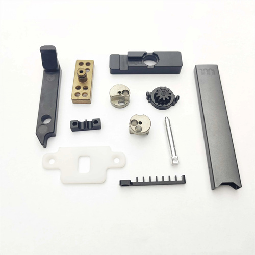
Milling tooth clutch
A sharp tooth clutch is a key component in mechanical transmissions that enables rapid connection and disconnection between shafts. Its structural characteristics are characterized by evenly distributed triangular teeth on the end faces, with a pointed tooth profile and straight tooth flanks. It is commonly used in applications requiring frequent direction changes, such as machine tool spindles and gearboxes. The key to milling a sharp tooth clutch is ensuring tooth profile accuracy, indexing accuracy, and tooth surface roughness. Commonly used machining equipment is a horizontal or vertical milling machine, combined with an indexing head to achieve uniform tooth distribution. The machining process must balance efficiency and precision to avoid defects such as tooth profile asymmetry and indexing errors.
Designing the tooth profile parameters for a sharp-tooth clutch is a crucial step before milling. Key parameters include the number of teeth Z , module m , addendum diameter d , root diameter d₁ , and tooth depth h . The number of teeth is determined by transmission requirements, with a common range of 3-36 teeth. Fewer teeth transmit greater torque. The module determines tooth size; a larger module results in a more robust tooth profile and greater load-carrying capacity. The tooth profile angle of a sharp-tooth clutch is typically 60° or 90° . The 60° tooth profile is suitable for light-load transmission, while the 90° tooth profile is suitable for heavy-load transmission. For a sharp-tooth clutch with a 90° tooth profile, Z=6 , and m=5mm , for example, the addendum diameter d = mZ = 30mm , the root diameter d₁ = d-2h = 30-2×5 = 20mm (tooth depth h = m=5mm ), and the addendum width is approximately 0.15m = 0.75mm. These parameters must be determined by calculation or table before machining and noted on the process drawing.
When milling a sharp-tooth clutch, the tool selection must match the tooth profile parameters. Commonly used tools are angle milling cutters or end mills. For clutches with a 90° tooth profile, a 90° double-angle milling cutter is used. The cutter angle must be perfectly aligned with the tooth profile angle, with a deviation of ≤±5°. The blade width should be less than the root groove width to avoid interference with adjacent teeth during cutting. For rough milling, a milling cutter with a smaller number of teeth (8-10 teeth) is used to improve cutting efficiency; for fine milling, a milling cutter with a larger number of teeth (12-16 teeth) is used to achieve better surface quality. The cutter material is selected based on the workpiece material. For machining steel, high-speed steel milling cutters (such as W18Cr4V) or carbide milling cutters (such as YT15) are used, while for machining cast iron, YG-type carbide milling cutters are used. When installing the cutter, ensure that the cutter axis is perpendicular to the worktable, with a deflection of ≤0.01mm/100mm. The radial runout of the cutter can be corrected using a dial indicator, with an error within 0.02mm.
The clamping and indexing of a sharp-tooth clutch are crucial for ensuring even indexing accuracy. Typically, a combination of an indexing head and a three-jaw chuck is used for clamping. One end of the workpiece is clamped by the three-jaw chuck, while the other end is supported by the indexing head thimble. This ensures that the workpiece axis aligns with the indexing head spindle axis, with radial runout ≤0.03mm. Before clamping, the workpiece’s reference surfaces (such as the end face and outer diameter) must be machined to a flatness of ≤0.02mm, and a perpendicularity of ≤0.01mm/100mm between the outer diameter and the end face. This ensures reliable positioning for subsequent indexing. Indexing is achieved by rotating the indexing head’s handle. After milling each tooth, the indexing handle is rotated to rotate the workpiece 360°/Z. For example, for a clutch with Z=6, the indexing handle must be rotated 60° per tooth. To improve the indexing accuracy, a side shaft pulley or optical indexing device can be used on the indexing head to make the indexing error ≤±30″. For high-precision clutches, recalibration is required after every 3-4 teeth are milled to prevent cumulative errors.
Milling process parameters are divided into two stages: roughing and finishing. The goal of roughing is to quickly remove stock. The cutting speed is 20-30 m/min (for high-speed steel cutters) or 50-80 m/min (for carbide cutters), the feed rate is 0.1-0.2 mm/r, and the cutting depth is two-thirds of the tooth depth, leaving a 0.5-1 mm allowance for finishing. Roughing is performed using a reverse milling method to reduce tool wear. Chips must be cleaned after each cut to prevent chip accumulation and affect the next cut. Finishing aims to ensure tooth profile accuracy and surface quality. The cutting speed is increased to 30-40 m/min (for high-speed steel cutters), the feed rate is reduced to 0.05-0.1 mm/r, and the cutting depth is the remaining allowance. Down milling is used to minimize tooth flank scratches. Adequate cutting fluid is required during milling. Extreme pressure emulsion (8%-10% concentration) is used for steel. Kerosene or dry cutting can be used for cast iron to cool and lubricate the tool and workpiece and prevent tooth burns.
Quality inspection must cover tooth profile accuracy, equal division accuracy, and surface quality. Tooth profile angles are tested using angle templates or universal angle gauges, with a deviation of ≤±10′. Pitch errors are measured on the tooth top circle using a dial indicator, with adjacent pitch errors ≤0.03mm and cumulative pitch errors ≤0.06mm. Tooth depth is measured using a depth vernier caliper, with a deviation of ±0.1mm. Surface roughness is inspected visually or with a roughness meter. The tooth surface Ra is ≤3.2μm and must be free of defects such as burrs, missing teeth, and burns. For important sharp-tooth clutches, an engagement test is also required. The paired clutches are engaged to check for sticking. The meshing clearance should be uniform, with a maximum clearance of ≤0.1mm. Strict process control and quality testing ensure the transmission accuracy and service life of the sharp-tooth clutch, meeting the requirements of mechanical transmission.