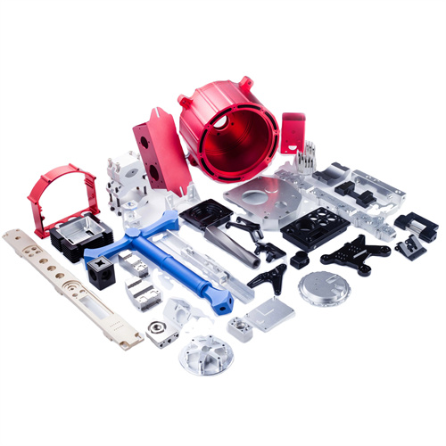
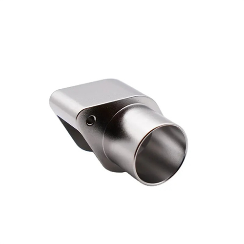
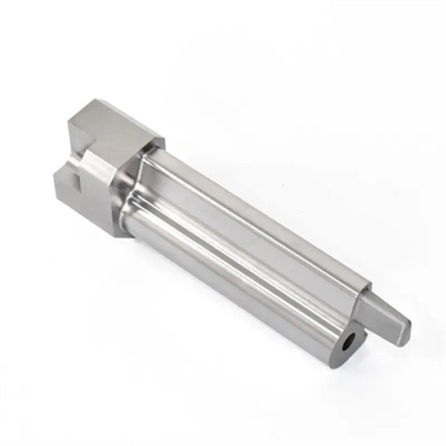
Clamping irregular parts on angle iron
Clamping irregular parts on angle iron is a common clamping method in machining. It’s suitable for parts with irregular shapes that can’t be directly clamped using three- or four-jaw chucks, such as brackets, housings, and flanges. The rigid support provided by the angle iron and the tightening action of bolts ensure stability during machining. Angle iron is an L-shaped cast iron part with two perpendicular working surfaces (perpendicularity error ≤ 0.01mm/100mm) and multiple T-slots or screw holes for mounting bolts and pressure plates. The key to clamping irregular parts on angle iron is accurate positioning, uniform clamping, and preventing deformation. A well-designed clamping solution based on the part structure is essential to ensure machining accuracy and safety.
The choice of angle iron should be determined based on the part’s size, weight, and processing requirements. Commonly used angle irons are categorized by structure into standard angle irons, faceplate angle irons, and adjustable angle irons. Standard angle irons are suitable for small and medium-sized irregular parts, with sizes ranging from 150mm x 100mm to 200mm x 150mm. They are lightweight and easy to operate. Faceplate angle irons are fixed to a faceplate and are suitable for large or complex parts. The faceplate diameter typically ranges from 300-600mm, offering excellent rigidity and positioning accuracy. Adjustable angle irons feature adjustable working surfaces (0°-90°) and are suitable for irregular parts requiring tilting, with an adjustment accuracy of ≤±5°. The working surfaces of angle irons are ground to a flatness tolerance of ≤0.02mm/100mm and a surface roughness of Ra ≤1.6μm to ensure a good fit with the part’s locating surface. When selecting angle irons, their dimensions should be larger than the part’s locating surface and their load-bearing capacity should be greater than 1.5 times the part’s weight to avoid deformation or vibration during clamping.
The positioning method for irregular parts on angle irons must follow the “three-point positioning” principle. Three reference surfaces (or lines or points) on the part are selected to determine the part’s position in the spatial coordinate system. The positioning reference surface should be a high-precision, large-area surface on the part, such as the bottom of a box or the end face of a flange. The positioning surface must be machined to a flatness tolerance of ≤0.03mm to ensure positioning accuracy. For parts without suitable flat surfaces, auxiliary positioning devices such as locating blocks or V-shaped irons can be used. The contact area between the locating block and the part should be ≥30%. V-shaped irons are suitable for positioning cylindrical or curved surfaces, with an angle of 90° or 120° between the two working surfaces and a positioning tolerance of ≤0.01mm. During positioning, a dial indicator should be used to align the machined surface of the part. For example, when machining a hole, the hole axis must be aligned with the lathe spindle axis, with radial runout ≤0.02mm. When machining a flat surface, the surface must be parallel to the worktable, with a parallelism tolerance of ≤0.01mm/100mm.
The clamping method must ensure that the part does not shift or deform during machining. Common clamping devices include bolt clamps, bow clamps, and eccentric clamps. Bolt clamps use the tension of bolts to press the part against the angle iron. The clamp should be located close to the workpiece, ≤100mm from the workpiece surface. Pads of equal height should be placed between the clamp and the part to prevent uneven force and deformation. Bow clamps are suitable for small parts, offering uniform clamping and ease of operation, but with lower clamping forces (≤5kN). Eccentric clamps utilize the self-locking action of the eccentric wheel for rapid clamping, making them suitable for mass production. Clamping forces can reach 10-20kN, with an eccentricity of 3-5mm. The clamping force should be adjusted based on the part material and rigidity. Cast iron parts can require a higher clamping force, while plastic materials such as aluminum alloys require a lower clamping force to prevent surface damage or deformation. The clamping sequence should be to clamp the area closest to the positioning reference first, followed by other areas, to avoid part shifting due to uneven clamping force distribution.
The key points of the process for clamping irregular parts on angle irons include pre-clamping preparation, alignment techniques, and precautions during processing. Before clamping, the burrs and oil stains on the part’s positioning surface and the angle iron’s working surface must be cleaned, and the surfaces must be polished with sandpaper to ensure a tight fit. For parts with poor rigidity (such as thin plates), auxiliary supports must be added, with evenly distributed support points and a gap of ≤0.05mm between the parts and the part. Alignment can be achieved using the “marking method.” First, mark the machining line on the part, then adjust the part’s position to align the machining line with the lathe spindle axis. The marking accuracy should be ≤0.1mm. Precision machining requires alignment using a dial indicator, measuring once per revolution and adjusting the part’s position until the error is ≤0.01mm. During machining, cutting parameters must be reduced, with cutting speeds 20%-30% lower than normal and feed rates of 0.1-0.2mm/r to avoid vibration caused by insufficient rigidity. Cooling must also be increased, and chips must be cleaned promptly to prevent chip accumulation that affects machining quality.
Common problems and solutions for clamping irregular parts on angle irons are crucial for ensuring machining quality. Part deformation is often caused by excessive clamping force or insufficient support. Solutions include reducing clamping force, adding auxiliary support, or using a spring-loaded pressure plate. Excessive perpendicularity between the workpiece surface and the reference plane is often due to poor perpendicularity of the angle iron’s working surface, requiring regrinding or replacement. Part loosening is often caused by loose bolts or slipping pressure plates. Bolt torque (usually 20-30 N · m ) should be checked and the anti-slip pressure plate replaced. For complex, irregular parts, combined angle iron clamping can be used. By combining multiple angle irons for multi-faceted positioning, the combined angle irons have a verticality error of ≤ 0.01mm/100mm . By properly selecting angle irons, positioning and clamping them correctly, and performing standardized operations, high-precision machining of irregular parts can be achieved to meet design requirements.