Machining of long step sleeve
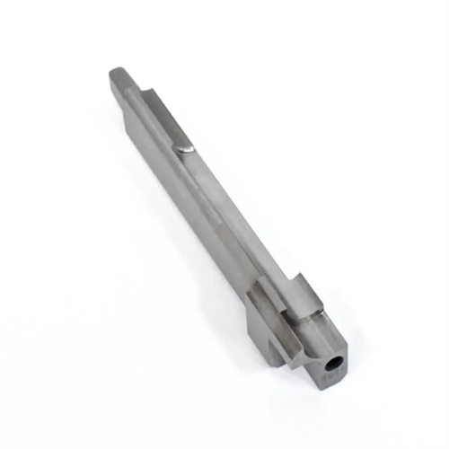
Long-step sleeves are sleeve-like components with a length-to-maximum-diameter ratio greater than 5 and multiple stepped holes or outer diameters. They are widely used in machine tool spindle boxes, reducers, hydraulic valve blocks, and other equipment for support, positioning, and sealing. Their structural characteristics are long axial dimensions, numerous steps, and high coaxiality requirements between the inner and outer diameters (typically ≤0.02mm). Machining these sleeves presents challenges such as poor rigidity, easy deformation, and difficulty controlling dimensional accuracy. Long-step sleeves are typically made of medium-carbon steels such as 45 steel and 40Cr. They require tempering treatment (220-250 HBW) to improve their overall mechanical properties. The machining process requires staged stock removal and a well-planned heat treatment process to ensure ultimate precision.
The machining process for long step sleeves should adhere to the principles of “roughing first, finishing second, exterior first, interior second, and primary first, secondary.” A typical process is: forging the blank → annealing (stress relieving) → rough turning the OD and end faces → rough boring the inner hole → aging (200°C x 4h) → semi-finish turning the OD, end faces, and step → semi-finish boring the inner hole and step → finish turning the OD and end faces → finish boring the inner hole and step → final inspection. For multi-step structures, the largest OD and deepest inner hole must be machined first to serve as a reference for subsequent machining. The distance between step surfaces must be accurately controlled to ±0.03mm, which can be guaranteed using the lathe’s longitudinal feed scale or digital display. The roughing allowance is 2-3mm, the semi-finishing allowance 0.5-1mm, and the finishing allowance 0.1-0.3mm. This gradual reduction in allowance controls deformation and avoids workpiece bending caused by excessive cutting effort.
The clamping method for long step sleeves needs to be adjusted according to the different machining stages. During roughing, a three-jaw chuck is used to clamp the outer diameter, with the chuck end extending 1/3 of the total workpiece length. The other end is supported by a steady rest. The three support blocks of the steady rest are evenly spaced, and the contact pressure with the workpiece outer diameter is controlled at 0.3-0.5 MPa to prevent workpiece deflection under cutting forces. During semi-finishing and finishing, to ensure the coaxiality of the inner hole and outer diameter, a “mutual reference” method is used: the inner hole is bored using the roughed outer diameter as the reference, and the outer diameter and step are then turned using the inner hole as the reference (using a mandrel for positioning). The clearance between the mandrel and the inner hole is ≤0.01mm, and the center holes at both ends of the mandrel are ground (to an H6 precision) to ensure positioning accuracy. For extra-long step sleeves exceeding 1000mm in length, a steady rest is required for auxiliary support. The contact point between the steady rest and the workpiece is located 50-100mm behind the cutting point to reduce vibration caused by cutting forces.
Machining the inner hole and step is the core of long step sleeve machining. Internal hole turning requires guaranteed dimensional accuracy (typically IT7-IT8 grades) and cylindricity (≤0.01mm/100mm). For rough boring, a carbide boring tool (YG8) is used at a cutting speed of 50-80m/min, a feed rate of 0.2-0.3mm/r, and a cutting depth of 1-2mm. Semi-finishing boring uses a YG6 tool at a cutting speed of 80-100m/min, a feed rate of 0.15-0.2mm/r, and a cutting depth of 0.5-1mm. Finish boring uses a high-speed steel boring tool (W18Cr4V) at a cutting speed of 30-50m/min, a feed rate of 0.05-0.1mm/r, and a cutting depth of 0.1-0.3mm. Extreme-pressure emulsion cooling is used to ensure an inner hole surface roughness Ra ≤1.6μm. When turning the step surface, it is necessary to ensure perpendicularity to the axis (≤0.01mm/100mm). Use a 90° external cylindrical turning tool and maintain a gap of 0.1-0.2mm between the blade and the root of the step to avoid interference between the tool and the workpiece. When cutting, turn the outer circle of the step first, and then finish turning the step surface to ensure the flatness of the step surface is ≤0.01mm.
Quality control of long step sleeves focuses on coaxiality, step distance, and surface quality. Coaxiality is checked using the dial gauge method: the workpiece is mounted on a runout gauge and the radial runout of the outer diameter and inner bore is measured with a dial indicator. The error must be ≤0.02mm. The step distance is measured with a vernier caliper or digital length gauge, with data recorded for each step measured. Deviations must be within ±0.03mm. Surface quality is inspected visually and with a roughness meter. Defects such as scratches, chatter marks, and burns must be avoided. The roughness of the outer diameter and inner bore must meet Ra≤1.6μm and Ra≤3.2μm, respectively. Common defects and solutions: If coaxiality is out of tolerance, the spindle must be recalibrated or the center rest position adjusted. If the step surface fails to meet the required verticality, the tool angle should be checked to ensure the lead angle is 90°±1°. If the inner bore tapers, the boring tool feed rate must be adjusted or the worn tool must be replaced. By strictly implementing the process route, optimizing the clamping method and cutting parameters, the processing qualification rate of the long step sleeve can be stabilized at more than 95%, meeting the equipment assembly requirements.