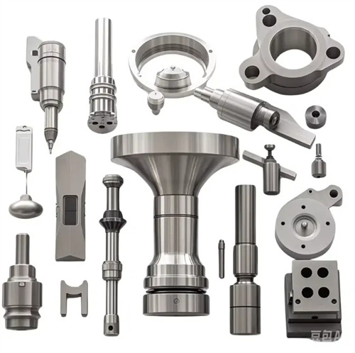
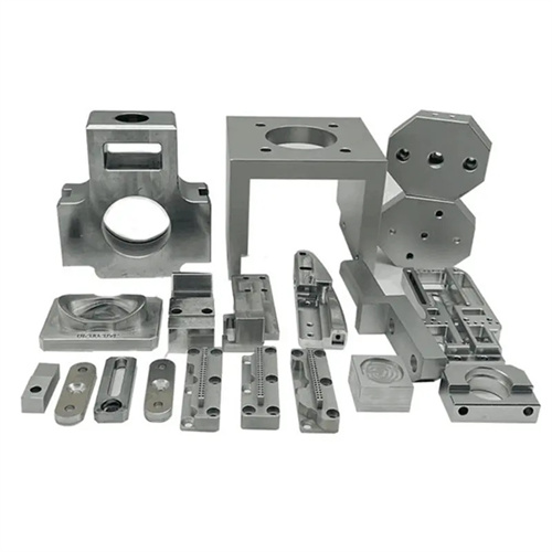
Machining of drilling machine spindle
The drill spindle is the core component of a drilling machine, driving the drill bit and transmitting torque. Its structural features include a tapered hole (for mounting the drill bit’s tapered shank), a shoulder, threads, and a keyway. Made primarily of 45 steel or 40Cr, it undergoes a quenching and tempering treatment (220-250 HBW) followed by partial hardening (the taper hole and journal surface hardness is 45-50 HRC) to ensure sufficient strength, wear resistance, and rotational accuracy. Machining of the drill spindle requires ensuring journal roundness (≤0.005mm), taper accuracy of the taper hole (1:20 ± 5′), perpendicularity of each shoulder (≤0.01mm/100mm), and thread accuracy (6g). The machining process is carried out in stages, with a well-planned heat treatment and machining sequence to achieve high precision and stability.
The processing route of the drilling machine spindle follows the principle of “separate rough and fine, benchmark first, and interspersed heat treatment”. The typical process route is: blank forging → normalizing (eliminating forging stress) → rough turning of the outer circle, end face and step → tempering treatment (220-250HBW) → semi-finishing turning of the outer circle, shoulder and tapered hole → scribing → keyway milling → rough grinding of the outer circle and tapered hole → local quenching (tapered hole and journal surface) → finish turning of threads → finish grinding of the outer circle, shoulder and tapered hole → final inspection. The blanks are made of high-quality carbon structural steel or alloy structural steel forgings. After forging, they are normalized (heated at 860-880℃, air-cooled) to refine the grain and improve cutting performance. During the rough turning stage, most of the allowance (3-5mm) is removed to leave sufficient allowance for subsequent processing. Tempering treatment gives the spindle good comprehensive mechanical properties. Semi-finishing prepares for fine grinding, leaving a 0.5-1mm grinding allowance for the outer circle and tapered hole. Local quenching improves the hardness and wear resistance of key surfaces. Fine grinding ensures final dimensional accuracy and form and position tolerances.
External turning and shoulder turning are fundamental to spindle machining on drilling machines. Rough turning of the external diameter is performed with a carbide external turning tool (YT15), cutting speeds of 80-100 m/min, feeds of 0.2-0.3 mm/r, and depths of cut of 2-4 mm. The journal diameter is 3-5 mm larger than the design size, with a surface roughness Ra ≤ 12.5 μm. Semi-finish turning of the external diameter is performed with a YT14 tool, cutting speeds of 100-120 m/min, feeds of 0.15-0.2 mm/r, and depths of cut of 0.5-1 mm. A 0.5-0.8 mm finishing allowance is left for the journal, with a surface roughness Ra ≤ 3.2 μm, shoulder flatness ≤ 0.03 mm, and perpendicularity to the axis ≤ 0.02 mm/100 mm. The shaft neck size accuracy must be ensured before fine thread turning. A carbide thread turning tool (YT15) is used for thread processing. The left-right cutting method is adopted with a cutting speed of 30-50m/min and a feed rate equal to the pitch (e.g., for an M30×1.5 thread, the feed rate is 1.5mm/r). The thread diameter tolerance is controlled within the range of 6g (upper deviation -0.032mm, lower deviation -0.144mm), and the surface roughness Ra≤3.2μm.
Machining and grinding the tapered hole are key to ensuring spindle accuracy on drilling machines. The taper hole should have a Morse taper (e.g., Morse taper #4, ≈ 1:19.212) or a metric taper (1:20) for mounting a drill bit or drill chuck. The taper accuracy requirement is ≤ ±5′, with a surface roughness Ra ≤ 0.8μm. For rough boring of the taper hole, a carbide boring tool (YT15) is used at a cutting speed of 60-80 m/min, a feed rate of 0.2-0.3 mm/r, and a depth of cut of 1-2 mm. The large-end diameter of the taper hole should be 1-2 mm larger than the design dimension, with a surface roughness Ra ≤ 12.5μm. For semi-finish boring of the taper hole, a YT14 tool is used at a cutting speed of 80-100 m/min, a feed rate of 0.15-0.2 mm/r, and a depth of cut of 0.5-1 mm. A 0.3-0.5 mm finish grinding allowance is left for the taper hole. Check with a taper plug gauge to ensure the contact area is ≥ 50%. The tapered hole is finely ground on a universal cylindrical grinder, using a grinding wheel grit of 60#-80#, a grinding speed of 30-35m/s, a feed rate of 0.01-0.02mm/r, and an emulsion (concentration 8%-10%) as the coolant. The taper plug gauge contact area is ≥80%, the surface roughness Ra ≤0.8μm, and the large end diameter dimensional accuracy is IT6 level.
Keyways and other details must be machined with guaranteed positional accuracy. The keyway width tolerance is H9 (e.g., for a 10mm wide keyway, the upper tolerance is +0.036mm, and the lower tolerance is 0), and the depth tolerance is ±0.1mm. This process is performed on a vertical milling machine using a keyway cutter in a single pass, with a cutting speed of 20-30m/min and a feed rate of 0.1-0.15mm/r. The symmetry between the keyway and the axis should be ≤0.05mm, which can be ensured using a dial indicator for alignment. Details such as the undercut and chamfer on the spindle end are completed during the semi-finishing stage. The undercut width and depth are selected according to standards (e.g., GB/T 3877.1-2017), and the chamfer should be 1×45° or 2×45° to avoid stress concentration. During quality inspection, use a roundness meter to measure the roundness of the shaft neck, a taper meter to detect the taper of the tapered hole, a dial indicator to measure the verticality of the shaft shoulder, a thread gauge to check the thread accuracy, and a projector to detect the symmetry of the keyway to ensure that all indicators meet the design requirements.
Final quality control of drilling machine spindles requires attention to rotational accuracy and stability. Dynamic balancing tests are performed before assembly, with unbalance maintained at ≤ 5g · cm to prevent vibration during high-speed rotation. Radial runout (at the journal) of the spindle is ≤ 0.01mm , and axial play is ≤ 0.005mm , which can be maintained through adjustments during spindle assembly. Common defects and solutions: Out-of-tolerance journal roundness is often caused by improper grinding wheel dressing during grinding, requiring re-dressing. Unsatisfactory taper of taper holes requires adjustment of the grinder table angle. Excessive thread accuracy requires calibration of the lathe leadscrew or replacement of the thread turning tool . Through strict adherence to process protocols and precise measurement, drilling machine spindles can achieve a service life of over 10,000 hours, ensuring drilling accuracy (hole diameter tolerance IT8-IT10 ) and surface quality ( Ra ≤ 3.2μm ).